| Calendar |
< May, 2024 >
| S |
M |
T |
W |
T |
F |
S |
| 28 |
29 |
30 |
01 |
02 |
03 |
04 |
| 05 |
06 |
07 |
08 |
09 |
10 |
11 |
| 12 |
13 |
14 |
15 |
16 |
17 |
18 |
| 19 |
20 |
21 |
22 |
23 |
24 |
25 |
| 26 |
27 |
28 |
29 |
30 |
31 |
01 |
|
|
| Animated Elephant Pull Toy |

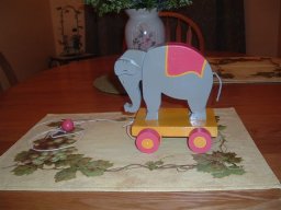
I recently decided to build a few toys as birthday presents for my youngest niece and nephew. I settled on an animated pull toy. Some time ago I found plans for an elephant whose head moved up and down as he was pulled along the floor. It looked simple enough and since I only had about 10 days to make two different ones this toy looked like the right one to start with. However, as I can never leave well enough alone, I decided to make them out of thicker wood than what the plans called for. This turned out to be a problem. The original plans called for ¼†and ½†stock. I increased the dimensions to ½†and ¾†to ensure less of a chance of the toys breaking. I later discovered that this decision affected the drive mechanism, which was a simple crank and connecting rod made from a coat hanger. The thicker stock caused the head to be a little heavier, which was enough to bind the crank every time. At this point I was committed so after some deep thought I figured a cam drive might just do the trick. I experimented with some scrap pieces and it worked. The original design can be found at The Woodcrafter Page (http://www.thewoodcrafter.net/proj/elptoy.php) a very good source of inspiration for any hobbyist woodworker. This page describes some of the details to alter the original design with that of the cam design.

Alterations for head pushrod assembly
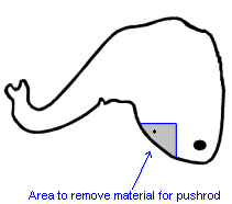
Follow the original plans for the elephant body but once the head is complete remove some material from the under side close to the pivot point allowing room for a 3/16†pushrod assembly. I used my drill press and a ¼†drill bit for this operation. I mounted the head upside down in a traditional parallel woodworking clamp and drilled some holes 90 degrees apart as indicated in the image above. Remove all the material from this area either by drilling, a carving knife or chisel. Once clean and smooth I suggest making a little pilot hole for the future placement of the brad that holds the pushrod in the pocket.
Alterations for Base
Follow the original plans for cutting the base, however, do not remove the section for the drive mechanism. Instead, working from the underside of the base, use a ½†Forstner Bit to remove about 75% of the material. This method provides a guide for the pushrod and prevents any little ones from getting their fingers caught in the drive mechanism. After you’ve smoothed out the recess you just created with the Forstner Bit you’ll want to drill the ¼†guide hole. Make sure to drill this hole centered 1/8†behind the center for the front axle and from the top of the base to avoid tear out. This hole is a critical hole. If it is not accurately placed, the elephant will not work. Don’t worry though if you make a mistake because you can just plug the hole with a piece of ¼†dowel rod and carpenters glue then start over.
Making the wheels and cam drive mechanism.
To make the wheels I used a 1 ¼†hole saw. A hole saw ensures the wheels will be perfectly round and that the hubs are perfectly centered. Make sure your pilot bit on your hole saw is a 1/8†bit or one that matches your choice of axles. Next, cut a cam from ½†stock using a 1†hole saw with the pilot bit removed. It is necessary to remove the pilot bit because the hub of the cam is not centered and use of the pilot bit may result in the weakening of the cam. After you smooth the cam using progressively finer sand paper drill the hub a ¼†off center, thus providing the means to move the head a ¼†up and down for every revolution of the axle. Now it is time to cut a few bearings to house the axle. Use a bit to drill these holes that is slightly larger than the axle. For the 1/8†axle use a 3/16†bit.
Pushrod Length
Now it is time to determine the pushrod length. It will be necessary for a rough assembly of the major parts to accurately determine this length. Put the elephant together using some wood screws to assemble the body and a temporary dowel to attach the head. Install the axle bearings on the base and insert the axles (make sure when you cut the axles to length to account for washers and the wheels. Insert a 3/16†dowel in the pushrod guide hole and into the head assembly. Holding the head at its most upright position, mark the pushrod dowel such that it is 1/8†from the top of the front axle. Disassemble the elephant and remove the pushrod. Cut the pushrod to the length indicated. Attach the pushrod to the head using a brad nail to properly secure it. Reassemble to make sure it fits correctly. Next, place the cam on the front axle directly below the pushrod. With the elephant upright, rotate the right side of the front axle in a clockwise rotation to confirm smooth operation of the head. Adjust axle bearings, cam, pushrod and head as needed.
"Action" Movie
Follow this link http://www.libertoenterprises.com/gallery1/main.php?g2_itemId=3088 to see a video of the completed toy in action.
Created on 08/20/2007 11:43 AM by admin
Updated on 08/20/2007 01:52 PM by admin
|

|
|
|

